Atari 1200XL UAV (Video) Mod
The Atari Xl line of personal computers did not include a connection from the on-board video chip to the video connector for the Chroma portion of the video, making true s-video output impossible without modification. This tutorial walks you through the Ultimate Atari Video (UAV) Rev. D modification installation.
Background - Why This Mod?
There are several options for updating the video on an old Atari XL computer, including the excellent (but often out of stock) Sophia 2 board, which essentially replaces the entire graphics chip (GTIA) and provides independent RGB/YPbPr/VGA and DVI outputs. The Sophia 2 was out of stock when I set about upgrading my stock 1200XL, so I went with the much more basic but still excellent UAV Rev. D board. I purchased the board from The Brewing Academy, who is the official licensee for the board. Here's what they have to say about the board:
These boards were developed by Bryan Edewaard and sold by him for a long time. He has now sold the rights for the rev. D version to The Brewing Academy and we are producing them for all machines. What does it do?
- Has an on-board regulator to create a clean video power source.
- Has a 3-channel video amplifier designed for 75 ohm loads.
- Has a pixel re-clocking circuit to remove skew and better align the 4 luminance signals into a perfect pixel edge.
- Has a carefully designed chroma-shaping circuit.
- An adjustable pot on the board which controls the phase between the chroma and luma signals. A nice side-effect of this that you can change the artifact colors. There's also a jumper to invert the chroma which swaps the positions of the artifact colors.
While, with the right cable, you can connect a stock 1200XL to a more modern LCD monitor, you would need to use the composite connector, which is pretty low quality. This mod will allow connection using s-video (or HDMI, if you have an s-video to HDMI adapter). This is the cable I'm using. It has both s-video and composite, so would also work on an un-modified XL.
Installing the Mod
A huge shout out goes to several users on the AtariAge message board who posted very helpful instructions and photos on this post, which I used to do my installation. I couldn't have done it without the help of that post. This guide is meant to be a true "idiot's guide" to installing the mod, without having to wade through multiple forum posts, but it wouldn't exist without them.
What You'll Need
Let's get started! You'll need:
- Some basic soldering skills
- A soldering iron
- Solder
- Flux (recommended)
- Some wire
- Wire snips
- A philips screwdriver
- A small flat-head screwdriver (a small jewelers or eyeglass screwdriver is perfect)
You'll probably also want:
- An anti-static mat
- A chip puller
- and some needle-nose pliers
This is all in addition to an Atari 1200XL Computer (you can find tutorials for other versions of the XL, like the 800XL or 600XL online...they're very similar, with slight changes to where things are soldered), and of course, the UAV Rev. D board.
Step 1: Remove the Case and the RF Shielding
I neglected to take photos of this part, but it's very simple. Below are the written instructions, but the first part of this video (for a different mod, but that doesn't matter) shows you how it's done as well.
- There are six screws on the bottom of the 1200XL case. Remove those and set them aside (I like to use small ramekins to keep groups of screws separate).
- Flip the computer over and carefully separate the top and bottom case. There are two ribbon cables connecting the top and bottom portions. Carefully disconnect the cables from the motherboard, allowing you to fully remove the top portion of the case (the part with the keyboard) and the attached cables. Set aside.
- There are six more screws attaching the motherboard to the bottom of the case. Some of these screws are also holding the RF shield in place (more on that in a bit). Remove the screws and set aside.
- Now, to remove the RF shield, use something flat (I used the flat part of a hex bolt, but use whatever you can find) to push the remaining tabs holding the top portion of the RF shield to the bottom portion. They should pop right through, allowing you to fully remove both portions of the metal RF shield. You can throw the RF shield away if you want. You can also re-install it later, but it's not really needed.
- You should now have the motherboard on its own. Set it on your anti-static mat.
Before we continue, here's a photo of the 1200XL motherboard with the locations of everything we're going to do in the next steps annotated. It might be a good idea to open the image up in a new tab and keep it handy for reference.
Step 2: Wire Up the UAV Board and Set the Jumpers
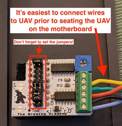
It's much easier to connect the wires to the UAV board before inserting it onto the motherboard. You can see from the annotated photo of the motherboard where each wire will go, so you can tell approximately how much wire to use for each. Cut each wire longer then you think you'll need, just in case. It's easier to shorten a too-long wire than it is to start over because your wire was too short.
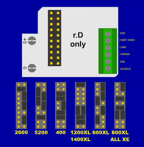
To the right you'll see a diagram that shows what each connector in the wiring block is used for, as well as the jumper settings depending on what computer you're upgrading. Be sure to set the jumpers according to the 1200XL section.
It also helps to use different colored wires for each connector so that it's easy to tell them apart later.
Note: the diagram and photo (below) are oriented on their side to make them easier to read. When you insert the board into the motherboard (in a later step), the wiring block will be pointing north. See the previous annotated photo for reference.
Here's a photo of my board with the wires attached and the jumpers set:
Step 3: Remove the 4050 IC (U27) and Insert the UAV Board
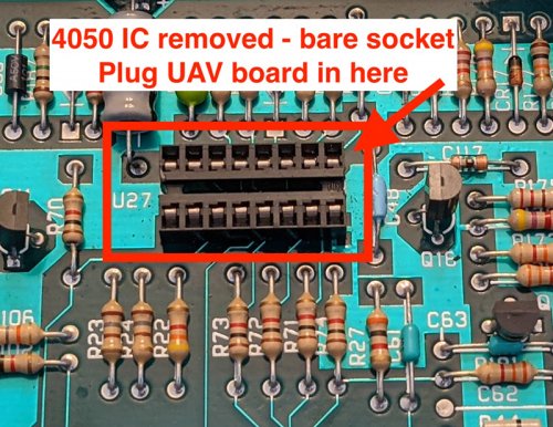
We need to make room for the UAV board to go. Luckily, the chip we're going to remove is (almost always) socketed, making it a simple matter of removing the chip, then inserting the UAV board. If you have a chip puller, it'll make removing the chip pretty easy. Mine was stuck a bit, but a little wiggling back and forth got it to come loose. If you don't have a chip puller, you can use your small flat-head screwdriver to gently lift (a little bit at a time) from each of the ends. You should feel a slight ridge for the flat head to slide under. Take your time. You're not worried about the chip, as you won't need it anymore, but you don't want to damage the socket.
Now simplly insert the UAV board into the empty socket. In the annotated photo, the side of the board with the wires attached will be towards the top of the photo. (You can also look at the photo of the completed board.
If for some reason your 4050IC isn't socketed, you'll need to de-solder the chip and install a socket. That's beyond the scope of this tutorial, but isn't all that hard (and there are plenty of video tutorials on YouTube).
Step 4: Solder the Composite and Luma Wires to the Motherboard
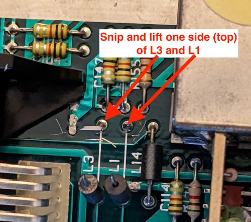
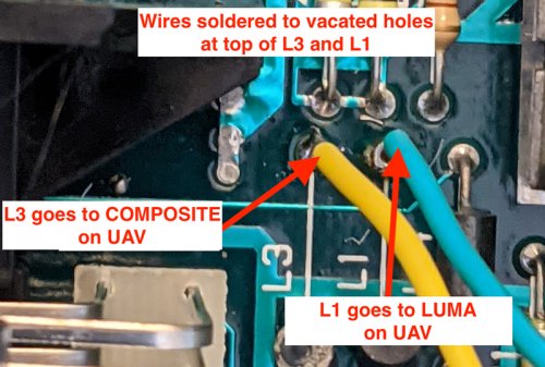
- Snip and lift the back pins of L1 and L3 jumpers. You only want to snip one side, and it'll be the side closest to the back side of the motherboard. (See the photo to the right)
- With the pin out of the way, solder the wire coming from the LUMA connector on the UAV board to the vacated spot at the top of L1. There should be a bit of solder left in the hole, but you will likely want to add a little bit more. Be sure not to expose too much wire. Just enough to make a good solder.
- Now, do the same thing with the COMP. VIDEO (Composite) wire from the UAV board to the vacated L3 hole.
- Optionally, you can use a hot glue gun to glue a portion of the wires to the top of the RF connector box. This will keep them from moving around when you take the case on and off.
Here's a photo of the wires after they've been soldered to L1 and L3:
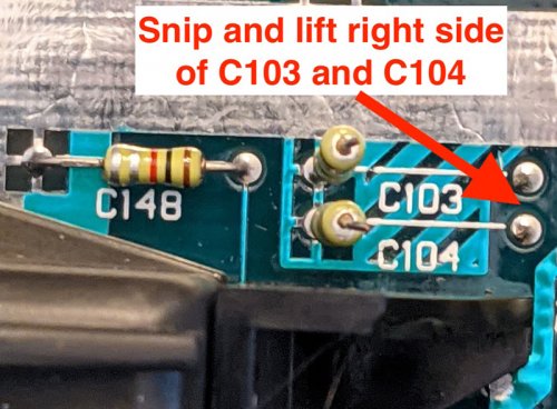
Step 5: Lift the Right Pins of C103 and C104
This one is pretty self explanatory. You're not going to solder anything here, but you want to snip and lift the right side of C103 and C104.
Step 6: Solder Wires for Color-In and Ground
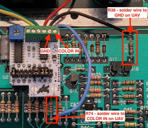
- Solder the wire from the COLOR-IN connecctor on the UAV board to the bottom of R74. You're not going to be snipping/lifting this time. Add it to the existing connection. R74 might be hard to read, but you can see where it is in the photo below. (For some reason it goes, left-to-right, R73, R72, R71, R74. R27 will be to the right of R74.)
- Solder the wire from the GND connector (either one) on the UAV board to the top of the R38 connector. This one is easier to see. Again, you're not snipping/lifting...just adding.
Here are COLOR-IN and GND connected to R74 and R38 respectively:
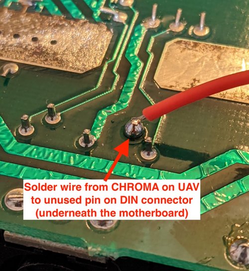
Step 7: Solder Wire from CHROMA to DIN Connector
 The final step! (Aside from putting everything back together...) We're adding the long-missing CHROMA feed to the monitor port.
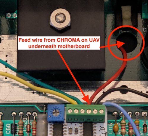
- Feed the wire from the CHROMA connector on the UAV board through the large hole just above the board.
- Solder the wire on the underside of the motherboard, to the vacant pin on the DIN (monitor) connector. It's pin 5, but the pins aren't in order. Looking at it from underneath, with the edge of the motherboard closest to you, it'll be the 2nd connector from the right. It'll also be the only one without a trace going to somewhere else. (See photo below)
Here's a photo of the underside of the motherboard, with the CHROMA wire connected to the vacant pin:
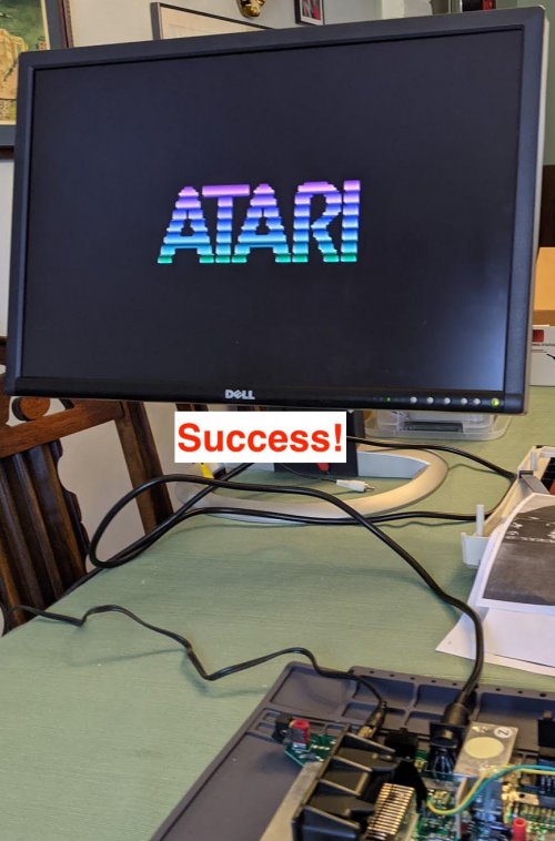
And that's it! You should test everything before putting the 1200Xl back together. Here's mine, showing off the splash screen in s-video glory!
And if you're interested, here's a photo of the completed board.